|
Main Unit
|

|
|
|
Recording Channels
|
8 channels
|
|
Recording Range
|
360° in the horizontal plane
±80° in the vertical plane
|
|
Output Data Rate
|
Depending on the number of processed channels, user selectable:
- 8000 Hz (2 channels processed)
- 4000 Hz (4 channels processed)
- 2000 Hz (8 channels processed)
|
|
Resolution
|
< 0.0002°
|
|
Noise
|
Full Bandwidth:
< 0.0028° RMS, < 0.018° peak-peak (search coil orientation:
horizontal 180°,
vertical 0°)
< 0.0035° RMS, < 0.024° peak-peak (search coil orientation:
horizontal 180°,
vertical 40°) |
|
200 Hz Bandwidth (internal low pass filter, 200 Hz Bessel 4th order):
< 0.0015° RMS, < 0.008° peak-peak (search coil orientation:
horizontal 180°,
vertical 0°)
< 0.0018° RMS, < 0.010° peak-peak (search coil orientation:
horizontal 180°,
vertical 40°) |
|
|
50 Hz Bandwidth (internal low pass filter, 50 Hz Bessel 4th order):
< 0.0004° RMS, < 0.002° peak-peak (search coil orientation:
horizontal 180°,
vertical 0°)
< 0.0007° RMS, < 0.004° peak-peak (search coil orientation:
horizontal 180°,
vertical 40°) |
|
|
Drift
|
< 0.1° within 30 minutes after power-on (warm-up), negligible
after warm-up
|
|
Linearity Error
|
Horizontal ±0.3° max. within 360° range
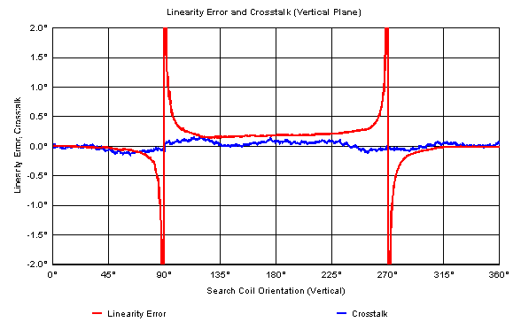
Vertical ±0.3° max. within ±80° range
|
|
Low Pass Filter
|
Digital low pass filter with user selectable characteristics per channel:
- Disabled (bypassed)
- Bessel 4th order (IIR): 500 Hz, 200 Hz or 50 Hz
- Butterworth 4th order (IIR): 500 Hz, 200 Hz or 50 Hz
- Moving average (FIR): 8, 16 or 32 taps
|
|
Front Panel
|
| Field Signals: |
- Frequency X-Axis: 105.794 kHz (note 1)
- Frequency Y-Axis: 113.932 kHz (note 1)
- Frequency Z-Axis: 122.070 kHz (note 1)
- Nominal Output Voltage: Depends on the used
coil frame (note 2)
- Maximum Output Voltage: 52 Vpp differential
measured
- Output Impedance: 0.2 Ohm max. |
|
| Preamplifier Interface: |
| - Power supply and data interface to the external preamplifier |
|
| Analog Outputs: |
- 24 analog outputs, user selectable data
format
- Voltage Swing: ±2 V, ±2.5 V, ±4 V, ±4.5 V or ±5 V (user
selectable)
- Resolution: 14 Bit
- Output Impedance: 200 Ohm typical |
|
| USB Interface: |
- USB 1.1 / 2.0 interface, bulk data
transfer
- Resolution of the transmitted output data: 21 Bit |
|
| Mains Power Switch: |
| - System power on / off |
|
| Display with Touch Screen: |
- 5" LCD with touch panel, 240 x 64
pixel
- User adjustable contrast and backlight
intensity
- Menu system to control the system configuration |
|
|
Rear Panel
|
Mains Power Input:
- 230 VAC ± 10 %, 50 Hz / 115 VAC ± 10 %, 60 Hz (250 VA max.)
|
|
Outline Dimension
|
255 x 110 x 310 mm (w x h x d)
|
|
Weight
|
6.5 kg
|
|
Preamplifier
|

|
|
|
Recording Channels
|
8 channels, user adjustable gain setting per channel
|
|
Input Impedance
|
600 Ohm typical (100 kHz)
|
|
Supply Voltage
|
±5 VDC, ±300 mA max. (power supply is provided by the main unit)
|
|
Outline Dimensions
|
76 x 35 x 154 mm (w x h x d)
|
|
Weight
|
420 g
|
|
Coil Frame
|

|
|
|
In General
|
Three coils with two turns each, arranged as a cube
Optional version “Removable Bars” available, which allows the
straightforward opening of the coil frame, e.g. to insert a primate
chair
|
|
Magnetic Flux Density
|
15 uT typical (note 3)
|
|
Coil Material
|
Anodized aluminum bars, cross section 8 mm
|
|
Coil Color
|
Various colors available, contact Primelec for further information
|
|
Dimension
|
Dimension L1 is freely definable within the
range from 250 mm to 700 mm,
the other dimensions (L2 to L5) are resultant |
 |
| L1 = |
250 ... 700 mm |
| L2 = |
L1 - 16 mm |
| L3 = |
L1 - 27 mm |
| L4 = |
L1 + 36 mm |
| L5 = |
L1 + 26 mm |
|
|
|
Weight
|
Depends on the coil dimensions,
for example approx. 5 kg for L1 = 700 mm
|
|
Search Coils
|

|
|
|
Material
|
Preferably double insulated copper wire, Ø 20um
|
|
DC-Resistance
|
100 Ohm max. (note 4)
|
|
Effective Area
|
0.5 cm^2 ... 100 cm^2 (note 5)
|
|
Weight
|
Depends on material, dimensions and manufacturing process, for example approx. 2 mg for a double insulated copper coil with
a diameter of 2 mm and 80 turns
|
|
Diagrams
|

|
|
|
Typical
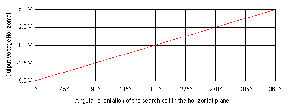
progression of the output voltage, horizontal plane (Note 6)

|
|
Typical
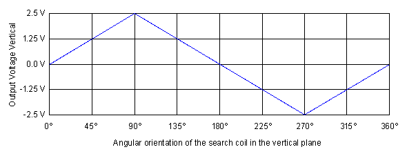
progression of the output voltage, vertical plane (Note 6)

|
|
Warm-Up drift
(Note 7)

|
|
Linearity
Error and Crosstalk (Note 7)


|
|
Distribution
of Angular Noise, based on 4000 Readings (Note 7)
|
|
Note 1:
|
Other frequencies for the field signals on request, contact Primelec for further information.
|
|
Note 2:
|
The nominal output voltage of each field signal is tuned at the factory to achieve the specified magnetic flux density and an optimal field homogeneity at the 3D-centre of the coil frame.
The tuned field signals may be attenuated by the operator in steps of
10 % down to zero.
|
|
Note 3:
|
The specified magnetic flux density refers to the nominal output voltage of the field signals.
The magnetic flux density may be reduced by the operator in steps of 10 % down to zero.
|
|
Note 4:
|
Higher DC resistance is applicable, possibly resulting in increased noise on the system’s output data.
|
|
Note 5:
|
Effective Area = n D^2 pi / 4 (where n is the number of turns and D
is the diameter).
Smaller effective
area is applicable, possibly resulting in increased noise on the
system’s output data. Larger effective area (up to 1000 cm²) is
applicable by reducing the magnetic flux density.
|
|
Note 6:
|
Output Mode: Angular Data, Output Swing: ±5 Volt
|
|
Note 7:
|
Used setup for the performance measurements:
- Coil frame L1 = 700 mm
- Search coil effective area = 10.8 cm², DC resistance = 4.8 Ohm
- Angular data acquired over the USB interface
- 8 channels processed
- Gain correction disabled
- Offset correction disabled
- Field signals magnitude = 100 %
- Preamplifier gain setting = 17
- Low pass filter disabled
|


