|
In General
|
|
Recording Channels
|
Two channels in the Basic System, expandable by the use of up to two additional channel pairs to six channels
|
|
AC Input Voltage
|
AC input voltage: 230 VAC ± 10%, 50...60Hz
(115 VAC ± 10%, 50...60Hz on request)
|
|
Power Consumption
|
300 VA max.
|
|
LED-Display
|
7-Segment (Mode Indicator)
|
|
Control Elements
|
Main switch,
multifunctional toggle-switch for the mode of each CPU Plug-In
|
|
Outline Dimensions
|
19" / 3 HU rack mountable or desktop case,
approx. 483 x 140 x 380 mm (w x h x d)
|
|
Weight
|
Basic system approx. 8 kg
Additional channel pair approx. 0.5 kg
|
|
Performance
(see also the diagrams below)
|
|
Output Data Rate
|
400 Hz
|
|
Recording Range
|
360° in the horizontal plane
± 70° in the horizontal plane
|
|
Resolution
|
< 0.1°
|
|
Noise
|
< 0.3° peak-peak (search coil orientation: horizontal 180°, vertical 0°)
< 0.8° peak-peak (search coil orientation: horizontal 180°, vertical 80°)
|
|
Drift
|
< 2° within 30 minutes after power-on (warm-up)
|
|
Linearity
|
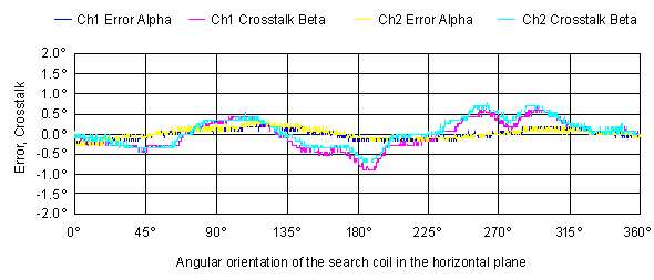
Horizontal < 0.7° deviation within 360°
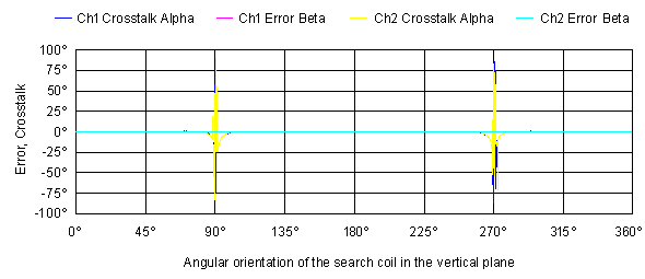
Vertical < 1° deviation between ± 70°
|
|
Analog Outputs
|
|
Output Voltage Swing
|
±9 V
|
|
Output Impedance
|
50 Ohm
|
|
Serial Interface
|
|
In General
|
One serial interface (RS-232) transmits the data of 2 recording channels
|
|
Parameters
|
38'400 bps, no parity, 8 data bits, 1 stop bit
|
|
Preamplifier
|
|
In General
|
Each preamplifier is located in a separate housing
|
|
Recording Channels
|
2 channels
|
|
Outline Dimensions
|
112 x 33 x 60 mm (w x h x d)
|
|
Weight
|
250 g
|
|
Coil Frame
|
|
In General
|
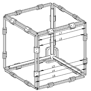
Three coils with two turns each, arranged as a cube
|
|
Magnetic Flux Density
|
23 uT typical
|
|
Coil Material
|
Anodized aluminium bars, cross section 8mm
|
|
Coil Color
|
Various colors available, contact Primelec for further details
|
|
Dimension
|
Dimension L1 is freely definable within the range from 250 mm to 700 mm,
the other dimensions (L2 to L5) are resultant |
 |
| L1: |
250 ... 700 mm |
| L2: |
L1 - 16 mm |
| L3: |
L1 - 27 mm |
| L4: |
L1 + 36 mm |
| L5: |
L1 + 26 mm |
|
|
|
Weight
|
Depends on the coil dimensions, for example approx. 5 kg for L1 = 700 mm
|
|
Search Coils
|
|
Material
|
Preferably double insulated copper wire, Ø 20µm
|
|
Weight
|
Depends on material, dimensions and manufacturing process,
for example approx. 2 mg for a double insulated copper coil with
D = 2mm and n = 80
|
|
DC-Resistance
|
75 Ohm max. (3 Ohm ... 40 Ohm typical)
|
|
Diameter
|
2 mm ... 40 mm typical (see also "Effective area")
|
|
Number of Turns
|
1... 630 typical (see also "Effective area")
|
|
Effective Area
|
2.5 cm2 ... 20 cm2 (Aeff = n D^2 pi / 4)
The range of the effective area specified above refers to the
typical magnetic flux density. If the flux density is reduced by attenuating the field signals to 20 % of their nominal values, the allowed effective area may be up to approx. 150
cm2
|
|
Diagrams
|
|
Typical progression of the output voltage
(horizontal plane)

|
|
Typical progression of the output voltage
(vertical plane)

|
|
Warm-Up drift (Notes
2 to 4)

|
|
Horizontal linearity and crosstalk to vertical, Beta at 0° (Notes
1, 2, 4)

|
|
Vertical linearity and crosstalk to horizontal, Alpha at 180° (Notes
1, 2, 4)


|
|
Distribution of angular noise (Notes
1, 2, 5)

|
|
Note 1:
|
Measured after 15 minutes warm-up delay with stepper-motor driven search coil under software control
|
|
Note 2:
|
Used coil frame: formed as a cube, s = 70 cm
Used search coil: Ø 15mm with 6 turns, placed in the 3D-center of the coil frame
The data was acquired over the serial interface
|
|
Note 3:
|
Measured with 6 channels working (i.e. max. internal power dissipation)
|
|
Note 4:
|
Channel 1 and channel 2 in parallel at the same search coil (i.e. identical input signal)
|
|
Note 5:
|
Each histogram is based on a recording with a total number of
readings of 12000
(30 seconds at 400 readings / second)
|


